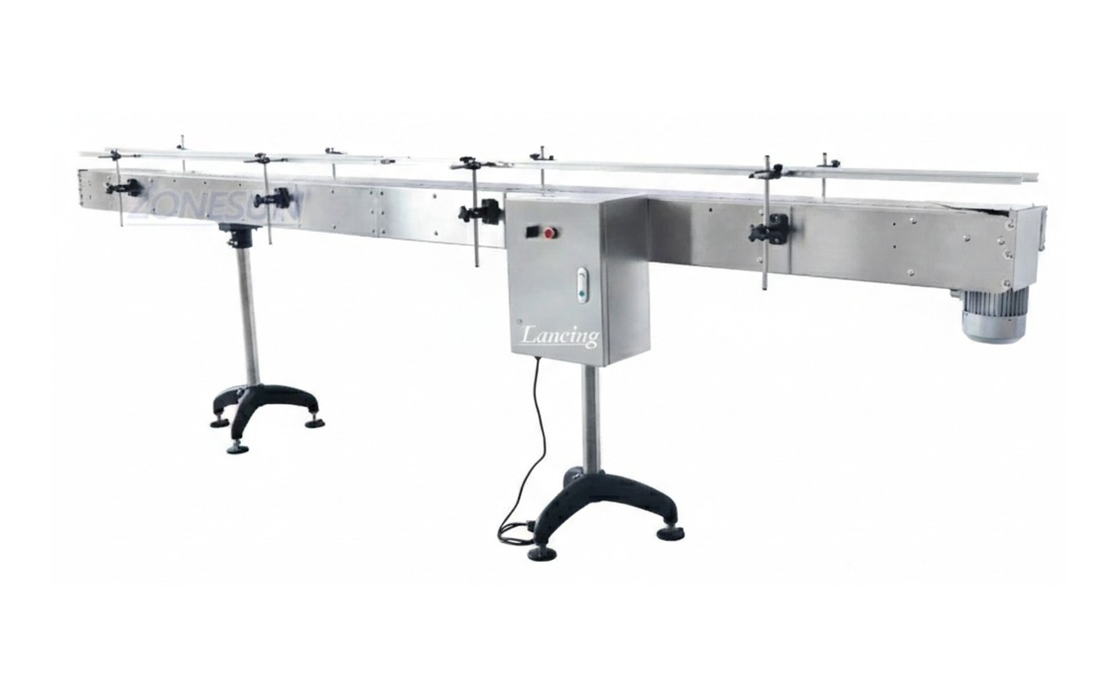
 General transfer
Belt conveyors
Clean, practical movement for cartons, bottles, tubs, trays and stable packaged goods.
Explore →Accumulation gives a packaging line breathing space. It can prevent a short stoppage at one point from stopping the whole line, but it must be planned around product stability, back pressure and available footprint.
Accumulation gives a packaging line breathing space. It can prevent a short stoppage at one point from stopping the whole line, but it must be planned around product stability, back pressure and available footprint.
A conveyor quote is more accurate when pack samples, layout drawings and target output are supplied with the enquiry.
Conveyor selection works best when transfer, accumulation and machine interfaces are planned together.
General transfer
Clean, practical movement for cartons, bottles, tubs, trays and stable packaged goods.
Explore →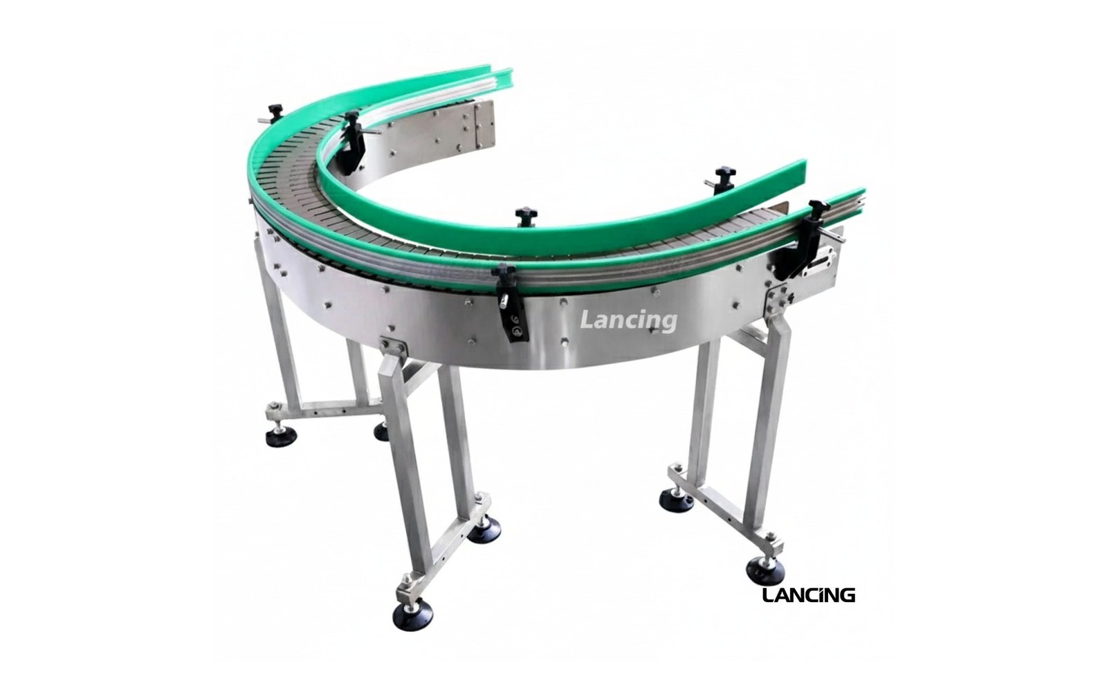 Bottle lines
Stable inline handling for bottles, jars and containers moving through filling, capping and labelling.
Explore →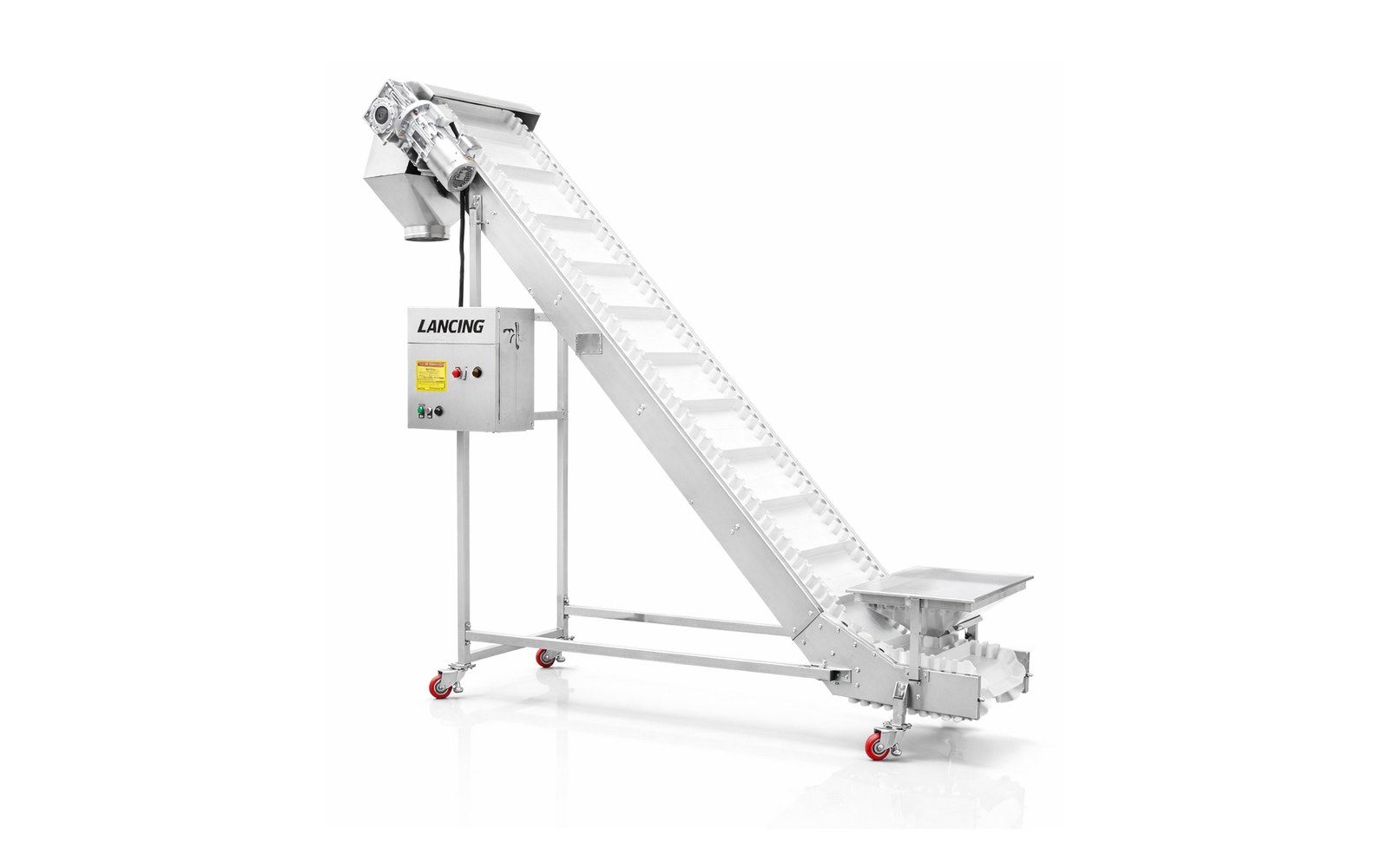 Elevation changes
Move packs between levels with belts, cleats, grip surfaces and layout support for safe transfer.
Explore → Compare your options
Check pack stability, transfers, widths, speeds, accumulation and integration before choosing a conveyor.
Explore →Clear answers for choosing conveyor options, planning a line layout and preparing quote details.
You may need accumulation if short stops, manual processes or machine speed differences regularly interrupt the whole line.
Accumulation is a controlled production buffer. It is not simply storage; it must preserve pack order, stability and flow into the next process.
Send pack dimensions, filled weight, line speed, available footprint, infeed and outfeed heights, photos of the existing line and details of connected machines.
Send your product details, line speed and available space to get advice on the conveyor route that fits your packaging line.
Accumulation is useful only when it absorbs a defined interruption and releases product without creating a new bottleneck. Begin with the line event: a cap refill, label change, reject-bin check, packing delay or short downstream stop. Record how long the upstream process should continue, the agreed product rate and what products can safely contact one another.
The theoretical capacity is straightforward: required buffer time multiplied by product rate. The physical conveyor is not. Usable capacity depends on product pitch or packing density, lane arrangement, guide geometry, contact pressure, entry and release control, and the space needed to prevent bridging or unstable restart.
A simple contact buffer may be acceptable for robust cartons or some containers. Decorated bottles, fragile jars, unstable packs or products with pumps and triggers may require reduced pressure, metered zones, multiple lanes or a rotary/recirculating arrangement. The design should state whether products touch, how pressure is limited and what happens at full capacity.
Accumulation should not be used to conceal a persistent speed mismatch. If the upstream machine continuously produces faster than the downstream machine can accept, any finite buffer will eventually fill. The rate schedule must distinguish temporary interruptions from sustained capacity differences.
Photoeyes can define zones or detect a full buffer, but sensor count alone does not define the logic. State when the upstream machine is inhibited, when the buffer runs, how product is released, what delay is acceptable and how the line recovers without a surge into the downstream machine. A VFD may support controlled speeds, but the sequence and product behaviour determine the usable result.
For compact bottle collection or feeding, compare rotary tables. For machine-to-machine signals and transfer detail, use the infeed and outfeed page.
| Quantity | Engineering relationship | What must still be tested |
|---|---|---|
| Theoretical product capacity | Required buffer time × agreed product rate. | Whether the stated rate is good output and whether upstream production continues for the full event. |
| Usable lane length | Product capacity × effective product pitch, adjusted for lanes and layout. | Actual pitch under contact or metered conditions and space lost at entries, curves and releases. |
| Available buffer time | Usable product capacity ÷ incoming product rate. | Product distribution, full-buffer detection and whether the buffer can release cleanly. |
| Recovery demand | Incoming rate plus desired buffer drawdown rate. | Whether the downstream machine can accept the temporary higher feed without instability. |
| Full-buffer response | Defined stop or inhibit sequence before capacity is exceeded. | Sensor reliability, timing, machine signal ownership and restart behaviour. |
A steady-state run does not validate accumulation. Test the line from an initially empty buffer, through normal running, a blocked downstream event, full or target capacity, upstream inhibition, downstream restart and return to normal. Observe product pressure, scuffing, tipping, bridging, sensor detection and any operator intervention.
The layout should leave access to clear a jam and maintain sensors, guides, belts or chains. Avoid creating a wide buffer that cannot be reached safely. Where products can fall, break or leak, the project risk assessment must define containment, guarding and safe recovery.
Document the exact samples, rate, stop duration and control settings. This provides a real acceptance record and prevents a theoretical count being mistaken for proven buffer capacity.
These answers define the evidence needed for a reliable specification and quotation.
Enough to absorb the agreed temporary stoppage or replenishment event. Start with buffer time multiplied by line rate, then validate usable capacity, product pitch, pressure and recovery on the actual layout.
Only for a limited time. If the downstream machine has a permanently lower sustainable rate, the buffer will fill. The long-term machine-rate mismatch must be resolved separately.
It is an accumulation approach intended to reduce product pressure compared with a continuously driving contact queue. The exact method can use zones, metering, speed control or other mechanisms and must be selected for the product.
After a stop, the buffer may need to empty while upstream production continues. The downstream machine and discharge route must accept that combined flow without causing a second jam or product surge.
Use a recorded test that starts from a known state, creates the agreed downstream stop, measures the stored products or time, verifies upstream response and proves stable release and recovery.
The first accumulation estimate is usually based on required buffer time and product rate, but the theoretical count is not the released capacity. The installed route also needs clear entry and discharge zones, sensor space, safe guide transitions, product pitch and enough room for the chosen release method. Curves, unstable containers and limits on product-to-product contact can reduce usable density further.
Define the stoppage being protected: which downstream machine stops, how long the event is expected to last, whether upstream equipment continues, slows or stops, and what happens when the restriction clears. Without that operating sequence, an accumulation length has no reliable performance meaning.
A buffer that fills correctly can still create a second bottleneck if it releases products too quickly, too slowly or without stable spacing. Recovery should establish how the downstream machine becomes ready, whether the discharge conveyor has a temporary speed margin, how metering or gating restarts and when upstream equipment returns to its normal state.
For a compact end-of-line area, compare outfeed accumulation tables and rotary tables. For a linear machine interface, use the infeed and outfeed conveyor guidance. The measured footprint and operating states should also be recorded in the line-layout checklist.
Capacity confirms how many products or how much time the buffer can absorb under the agreed condition. Pressure acceptance confirms that products, labels, closures and guides remain within the permitted contact condition. Controls acceptance proves normal flow, approaching-full response, full-buffer response, upstream stop and controlled restart. Passing one of these tests does not prove the others.
| Line state | Required definition | Evidence to record |
|---|---|---|
| Normal flow | Nominal product pitch, conveyor speed and machine-ready condition. | Stable running and transfer with the limiting formats. |
| Downstream stop | Stop signal, sensor response and whether upstream continues or slows. | Buffer fill sequence, product contact and time to the next control state. |
| Approaching full | Warning level, upstream speed reduction or controlled hold. | Sensor reliability and product behaviour at the defined density. |
| Full buffer | Upstream stop, fault indication and safe retained condition. | No uncontrolled pressure, overflow, tipping or loss of tracking. |
| Restart | Downstream-ready confirmation, release method and speed relationship. | Stable discharge without flooding the next machine. |
| Recovery complete | Condition for returning all equipment to normal control. | Buffer clear time and repeatable restoration of normal product pitch. |
Use the least stable and most contact-sensitive products as well as the nominal format.
Usable capacity must allow for product pitch, curves, guide clearances, sensor zones, entry and discharge space, allowable product contact and a controlled restart. A physical trial establishes the capacity that can be used reliably.
Create the agreed downstream stop, record how the buffer fills, confirm the upstream response, then restart the downstream machine and observe product release until normal flow is restored. Repeat with the limiting product formats.
Not while upstream continues at the same rate. Recovery needs temporary downstream capacity above the arriving rate, a controlled reduction or stop upstream, or another agreed production sequence that creates a positive clearing margin.
Nominal capacity is only one part of an accumulation duty. The line must detect the developing block, store products without unacceptable contact, release them in a controlled order and recover faster than new product arrives.
Define the incoming rate, required interruption time, usable storage zone and downstream recovery capability. Exclude unstable entry and discharge areas from the assumed capacity. Then create the agreed stop during a witnessed trial and record the product arrangement, full signal, upstream response and release pattern.
If products mark, lean, nest or rotate, revise the contact method or buffer form rather than relying on a theoretical quantity. The acceptance plan should include normal flow, nearly full, full, fault, reset and restart states.
Coordinate the controls and interlocks guide, FAT/SAT checklist and troubleshooting guide.
Useful accumulation is measured by how the line absorbs and recovers from a defined interruption without damaging or losing control of the product.
Controlled accumulation has a defined capacity, product-contact limit, full condition, release sequence and response from the upstream and downstream machines. Product crowding simply allows packs to collect until physical pressure or lack of space stops the flow. The first can protect production; the second can create scuffing, tipping, bridging or an unpredictable restart.
The release should restore the required product pitch without sending an uncontrolled surge into the downstream machine. Define when the first zone starts, how upstream zones follow, which sensors confirm space and how speed ramps are coordinated. Test the full-buffer condition because a release that works with a few products may fail when the entire buffer is occupied.
Accumulation can be harmful when products are easily scuffed, unstable under contact, fitted with delicate closures, wet, hot, soft or unable to tolerate sustained back pressure. Damage may also occur at guide transitions or during a sudden release. Establish the permitted contact and duration, then choose low-pressure, single-file, mass-flow or rotary handling only after sample testing.
Record the interruption duration absorbed, number of acceptable packs stored, response when full, downstream restart sequence, time to return to normal flow and any product damage or reject increase. Compare the same defined stop before and after the buffer is introduced. A larger accumulation area is not proof of improvement unless the complete recovery sequence is repeatable.
Physical conveyor area does not by itself establish useful accumulation. The accepted capacity depends on product density, permitted contact, inflow, release rate, sensor positions and the time required for the downstream machine to recover. Record the entry and discharge states as well as the product quantity or elapsed time that can be absorbed without damage or loss of control.
| State to prove | Evidence | Failure to prevent |
|---|---|---|
| Downstream stop | Time from stop signal to full usable buffer with the actual inflow. | Overflow, excessive back pressure or uncontrolled contact. |
| Buffer full | Full-state sensor, upstream response and product position. | Continued feed into a full zone or an unstable pack queue. |
| Downstream recovery | Release rate, product pitch and time to restore the normal level. | Restart surge, starvation or repeated cycling. |
| Sensor uncertainty | Defined response to blocked, dirty or inconsistent level detection. | Assuming capacity when the buffer state is not known. |
Where the buffer relies on photoeyes or product counting, define the real target and line state using the sensor guide. Keep the measured results with the layout and controls schedule rather than presenting a theoretical footprint as guaranteed production capacity.
A buffer can hold products successfully yet still cause a downstream fault if it releases a dense queue into a single-file machine. Define whether products leave in contact, at a controlled pitch, in one lane or across several lanes, and how the release changes after a short stop.
Where the buffer feeds coding, checkweighing, inspection or automatic packing, use lane merging and singulation planning to establish the outgoing condition. If products must stop at a station, review indexing conveyor control.
Buffer capacity is only useful if the products leave in a condition the next operation can accept. Before choosing single-file or wider accumulation, state whether the line must preserve exact sequence, maintain separation between batches or simply hold identical packs temporarily. These duties can lead to different layouts even when the required buffer time is the same.
For an order-sensitive process, ask how each product is associated with its coding, inspection or packing record while it is in the buffer. Do not assume a recirculating or mass-flow arrangement preserves entry order. Prove the required behaviour with identifiable trial packs and an agreed release sequence. Where all packs are interchangeable, confirm the physical contact limit instead; decorated or delicate products may require a low-pressure handling method.
Include batch clearance in the operating plan. Show how the last product from the previous batch is identified, how retained packs are removed or released and how the buffer is checked before the next batch begins. Test this at the real entry and discharge points. The result should define both usable storage and the restrictions on mixing, sequence and product contact.
No. Sequence depends on the layout and release method. Specify and demonstrate order preservation if downstream data or production requires it.
Identify the last previous-batch pack, account for retained products, clear the entry and discharge routes, and confirm the buffer state before the next batch.