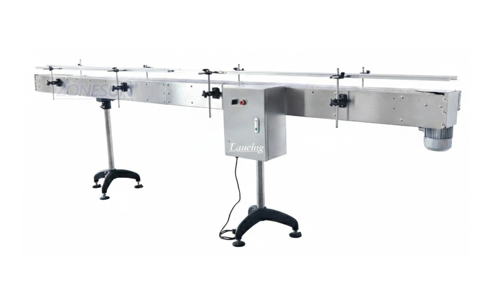
 General transfer
Belt conveyors
Clean, practical movement for cartons, bottles, tubs, trays and stable packaged goods.
Explore →Slat chain and modular chain conveyors are widely used where bottles, jars or containers need stable inline movement through filling, capping, labelling and coding. Guide rails, transfer plates and bottle stability are central to the specification.
Slat chain and modular chain conveyors are widely used where bottles, jars or containers need stable inline movement through filling, capping, labelling and coding. Guide rails, transfer plates and bottle stability are central to the specification.
A conveyor quote is more accurate when pack samples, layout drawings and target output are supplied with the enquiry.
Conveyor selection works best when transfer, accumulation and machine interfaces are planned together.
General transfer
Clean, practical movement for cartons, bottles, tubs, trays and stable packaged goods.
Explore →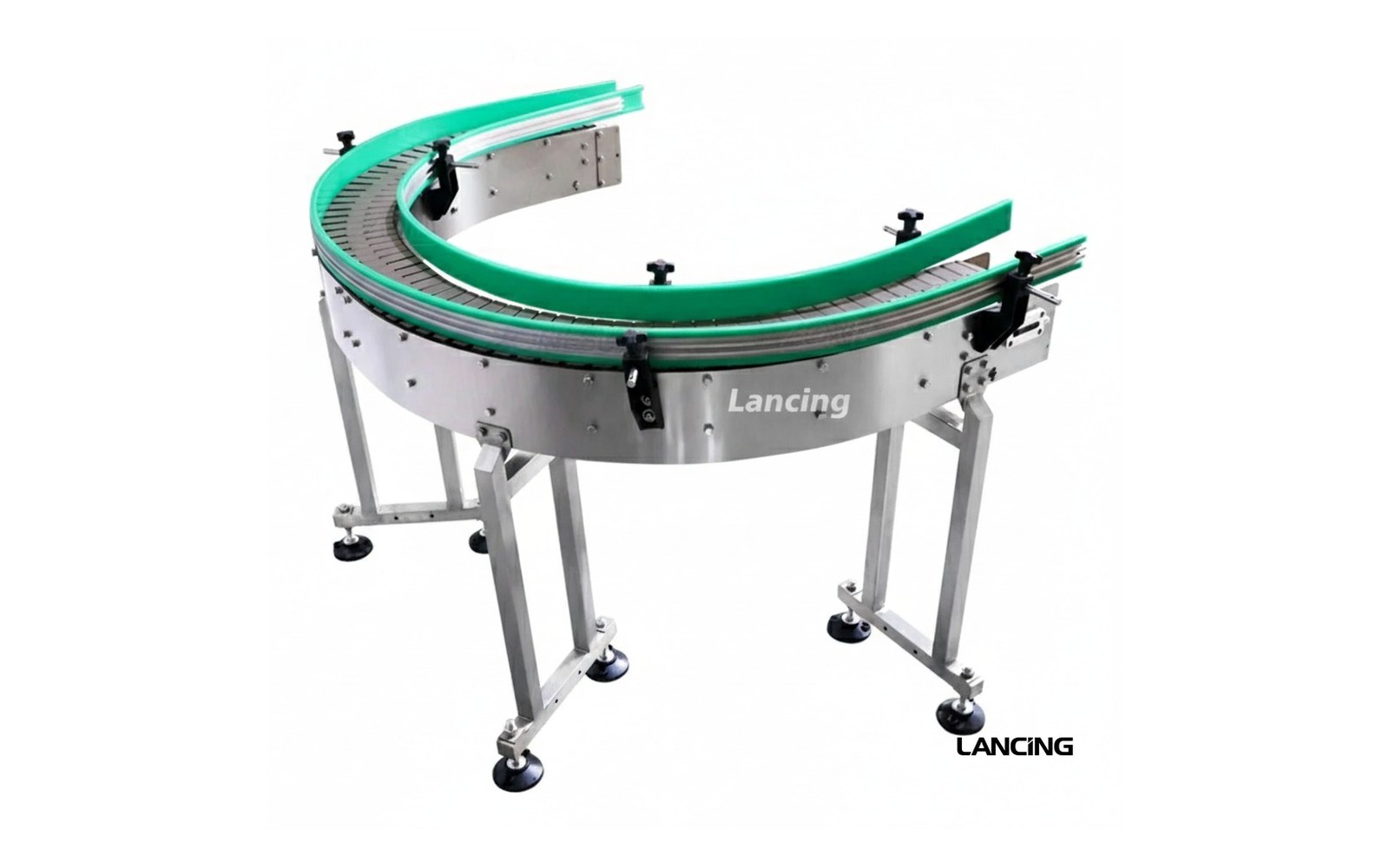 Bottle lines
Stable inline handling for bottles, jars and containers moving through filling, capping and labelling.
Explore →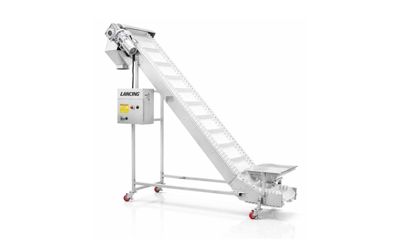 Elevation changes
Move packs between levels with belts, cleats, grip surfaces and layout support for safe transfer.
Explore →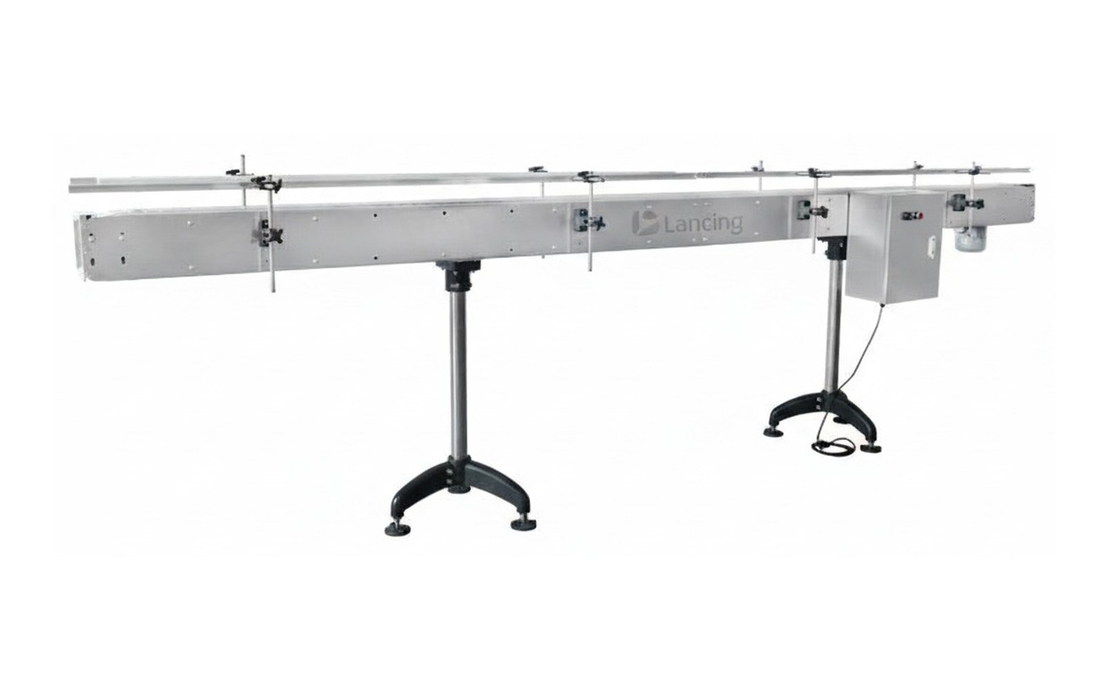 Compare your options
Check pack stability, transfers, widths, speeds, accumulation and integration before choosing a conveyor.
Explore →Clear answers for choosing conveyor options, planning a line layout and preparing quote details.
Yes. They are a common choice for bottles because guide rails, chains, curves and accumulation can be configured around container handling.
Yes. They are often used to connect fillers, cappers, labellers, coders and rotary tables in bottle packaging lines.
Send pack dimensions, filled weight, line speed, available footprint, infeed and outfeed heights, photos of the existing line and details of connected machines.
Send your product details, line speed and available space to get advice on the conveyor route that fits your packaging line.
Slat or tabletop chain conveyors are a common starting point for bottles, jars and containers moving through filling, capping and labelling stages. The chain provides a defined guided route and can follow straight or curved layouts, but stable performance still depends on the container base, guide-rail contact, transfer geometry, speed relationship and acceptable accumulation pressure.
The specification must identify the actual chain width and support requirement, not only the nominal container diameter. Tall, light, soft-walled, oval or trigger-spray containers can react differently to the same guide setting. Empty and filled samples should be reviewed because filling changes mass, centre of gravity and friction.
Guide rails should contact a stable part of the container and remain clear of labels, pumps, handles or decorative surfaces where contact would cause damage or rotation. Adjustment should cover the product range with repeatable settings. In curves, inner and outer guide geometry must work with the chain path and product centre of gravity.
Accumulation changes the duty. Containers may contact one another or the guides while the chain continues underneath, which can create pressure, scuffing, noise and instability. Confirm whether the product can tolerate contact and whether a low-pressure, metered or non-contact buffer is needed instead.
The transfer into a filler, capper or labeller can be limited by dead plates, timing screws, starwheels, gating, side belts or machine-specific guides. Record the height, gap, speed, product pitch and control state at each point. A good straight-run test does not prove a difficult machine transfer.
If the product base must be exposed for coding or inspection, a coding and inspection conveyor or side-grip section may be needed. If the project requires automatic bulk bottle orientation, continue to Bottle Unscramblers UK rather than treating the conveyor as the unscrambler.
| Specification field | Project definition | Verification |
|---|---|---|
| Chain type and usable width | Support width, straight or flexing route and product-base contact. | Container samples and route drawing. |
| Length, curves and working height | Measured route with radius, direction changes and interface datums. | Site survey and machine drawings. |
| Container load and pressure case | Maximum product mass and blocked-outfeed accumulation condition. | Filled samples and operating sequence. |
| Speed and drive | Good output, chain speed range, drive location, access and control method. | Machine-rate schedule and controls review. |
| Frame, chain and wear materials | Cleaning, corrosion, wear, lubrication and product-contact requirements. | Site environment and maintenance standard. |
| Side guides | Rail profile, height, contact zone, adjustment and format settings. | Full sample range and decorated-product review. |
| Transfers | Dead plate, chain-to-chain, machine entry/exit and gap support. | Interface drawing and product trial. |
| Accumulation method | Contact, low pressure, metering, lane or rotary buffer requirement. | Defined stop duration and product-contact limit. |
| Controls and sensors | VFD, photoeyes, blocked-line zones, gates and machine signals. | Functional description and signal list. |
| Ingress protection and guarding | Exposure, washdown method, return-path access and moving-part protection. | Environmental and risk assessment. |
The chain return, wear strips, sprockets, bearings and drive should be accessible for inspection. Cleaning debris from only the top surface is not enough if residue can collect under the chain or around the return path. The agreed cleaning method should determine access, drainage, material compatibility and whether components are removed or cleaned in place.
Noise can come from chain speed, dry running, worn wear strips, poor sprocket engagement, product contact and guide friction. Do not accept a generic noise expectation without defining the operating product and condition. Maintenance should include chain condition, elongation or engagement as applicable, wear surfaces, guides, fasteners, sensors, drive and guards.
For a straight route carrying stable cartons or trays, a belt conveyor may be simpler. For short bottle buffering, compare rotary tables and accumulation conveyors.
These answers define the evidence needed for a reliable specification and quotation.
No. It is a strong starting point for guided bottle routes, curves and machine linking, but belt, modular belt, side-grip or rotary solutions may suit a particular base, cleaning method or interface better.
The guide should contact a stable part of the container without interfering with labels, handles, pumps or closures. Use the tallest, shortest and least stable samples to set the adjustment range and contact zones.
They can in some duties, but the acceptable contact pressure, scuffing, noise and restart behaviour must be checked. Fragile, decorated or unstable containers may need metering or a lower-pressure accumulation method.
Common causes include height mismatch, excessive gap, sudden speed change, poor guide transition, base features and a high centre of gravity. The exact cause should be confirmed with samples and slow-motion observation.
Inspect chain condition, sprocket engagement, wear strips, return path, guides, bearings, drive components, sensors, guards and fasteners. Use the final component references for the spares schedule.
A slat-chain route that runs one bottle well is not yet a multi-format conveyor. The practical changeover is defined by the limiting containers: the smallest base, the tallest centre of gravity, the heaviest filled pack, the softest sidewall and any closure or decoration that restricts guide contact. Group formats by handling behaviour rather than nominal fill volume alone.
Create fixed measurement datums for adjustable rails, sensors and machine-entry guides. A handwheel position or visual estimate is useful only when it returns the conveyor to a verified setting. Where curves are included, record inner and outer rail settings independently because a change that looks acceptable on a straight may still create rotation or tipping through the bend.
When the downstream machine stops, the conveyor may continue moving under stationary bottles. The resulting product contact, guide friction and pressure depend on the chain route, bottle surface, filled weight, line speed and control sequence. The acceptance test should therefore include the agreed blocked period and the real restart logic, not only uninterrupted running.
If bottles lean, rotate or climb at the point where the queue forms, compare the route with the accumulation conveyor guidance. If instability starts at a machine hand-off, use the transfer-point review. Adjustable rails should be checked against the dedicated guide-rail planning page.
Tipping at a transfer can be caused by a height mismatch, unsupported base feature, abrupt guide transition or speed change. Rotation can result from unequal guide contact or a closure touching one rail. Scuffing may begin during accumulation rather than normal running. Noise can indicate product contact, dry running, wear-strip condition or poor engagement. Record the first location and line state where the symptom appears before changing several settings at once.
| Setting or condition | What to record | What the trial must confirm |
|---|---|---|
| Straight guide rails | Distance from a fixed datum and permitted contact zone. | Stable running without label, handle, pump or trigger interference. |
| Curve guides | Inner and outer settings for each format family. | No tipping, wedging or uncontrolled rotation through entry and discharge. |
| Chain speed | VFD or control setting and relationship to adjacent machines. | Stable transfer, spacing and recovery at the agreed production state. |
| Photoeyes and stops | Position, sensing method, delay and blocked-line response. | Reliable detection of the limiting transparent, reflective or closely spaced products. |
| Machine interface | Guide, dead-plate, starwheel, timing screw or side-belt setting. | Repeatable hand-off at normal running, stop and restart. |
| Blocked outfeed | Stop duration, queue location and upstream control response. | Acceptable pressure, product condition and controlled restart. |
The changeover record should be based on actual product trials and fixed reference points.
Only when the full bottle range remains stable and the guide contact zone is suitable at that setting. Mixed formats normally need recorded guide positions or repeatable adjustment datums, checked with the smallest, tallest and least stable samples.
Filling changes mass, centre of gravity and friction at the base. Closure application can add height or an overhanging pump or trigger, so empty, filled and closed conditions should be tested separately.
Record guide positions from fixed datums, curve settings, sensor positions, chain-speed or VFD settings and machine-interface adjustments for each approved format. The record should identify the sample and trial condition used.
Slat-chain routes depend on more than chain width. Bottle stability can change through curves, speed transitions, blocked discharge and guide adjustments, especially when empty and filled formats behave differently.
Record guide position, transfer alignment, sensor location and the product state used during the test. Observe the least stable bottle at curve entry and exit, during accumulation and after restart. If a closure, pump, trigger or label limits side contact, identify that restriction before the guide profile is released.
Where the base must remain open for coding, inspection or drainage, a side-grip section may be more appropriate than forcing the slat-chain route to solve the duty. Cleaning access should include wear strips, return chain, guides and trapped product areas.
Compare the side-grip conveyor guide, then use the sample-trial and cleaning/changeover checklists.
Slat-chain performance depends on the complete chain path, guide setting and release sequence, not only the top surface that carries the container.
Wear strips support and guide the chain through the conveyor route. Their condition and alignment affect chain stability, friction, noise, tracking and the quality of transfers. Uneven wear can alter the carrying surface or increase load on the drive. Inspection access and the replacement method should therefore be considered during layout review, not only after the line enters production.
A wider or less stable container may contact guides differently, while a lighter or more easily marked pack can react differently to the same accumulation density. Changed guide height, chain speed, closure projection and release timing can all increase contact pressure. Repeat the blocked-outfeed and restart test with each limiting format rather than assuming one setting represents the whole range.
Use more than one speed zone when a controlled change in pitch or flow is required between accumulation, processing and discharge sections. The reason for each zone must be explicit: create separation, match a machine, reduce contact or recover from a stop. The zone boundaries, sensors and ramp behaviour should be tested with full and starved product conditions.
Record the part reference, installed position, guide setting, chain or transfer height, direction of flow, sensor position and the product formats tested. Then repeat the relevant acceptance conditions, including normal running and blocked restart. A maintenance record should show that the original product-control geometry has been restored, not only that the conveyor moves.
A bottle may rotate or move laterally as it passes guide changes, curves and chain transfers. That movement affects both mechanical stability and the optical surface presented to a photoeye. Clear, glossy or partly labelled containers should be proved at the intended guide setting and through the closest permitted product pitch.
Record the chain, sprocket and wear-strip references with the accepted guide and sensor settings. After maintenance, confirm the chain path, guide clearance and detection signal with representative bottles before returning the line to production. Continue with the product-detection sensor guide and critical-spares guide.
Slat chain gives a continuous support surface for many bottles and jars, but a narrow, shaped or highly presentation-sensitive pack may still rotate, tip or contact the wrong surface. Test the complete product state through transfers, stops and guide transitions.
Compare puck conveyor systems for a carrier through several stations, side-grip conveyors for a local base-access duty and lane-control systems where several slat streams must combine or divide.