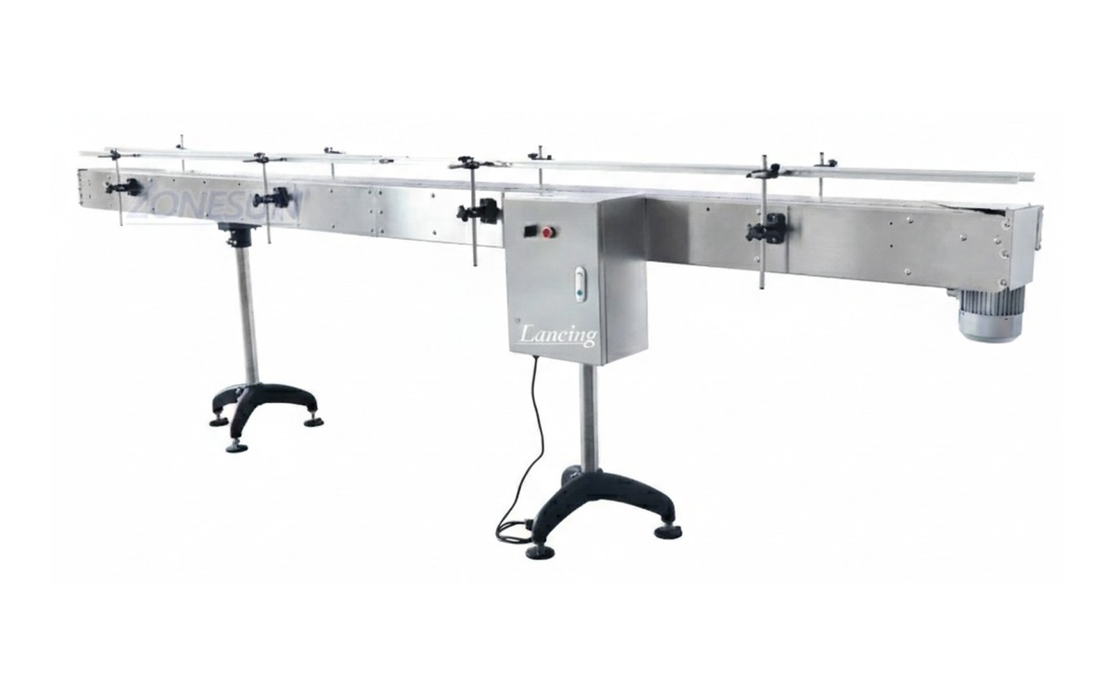
 General transfer
Belt conveyors
Clean, practical movement for cartons, bottles, tubs, trays and stable packaged goods.
Explore →Infeed and outfeed conveyors control how packs arrive at and leave each machine. They are critical when spacing, stability, timing, rejection or operator intervention affects line performance.
Infeed and outfeed conveyors control how packs arrive at and leave each machine. They are critical when spacing, stability, timing, rejection or operator intervention affects line performance.
A conveyor quote is more accurate when pack samples, layout drawings and target output are supplied with the enquiry.
Conveyor selection works best when transfer, accumulation and machine interfaces are planned together.
General transfer
Clean, practical movement for cartons, bottles, tubs, trays and stable packaged goods.
Explore →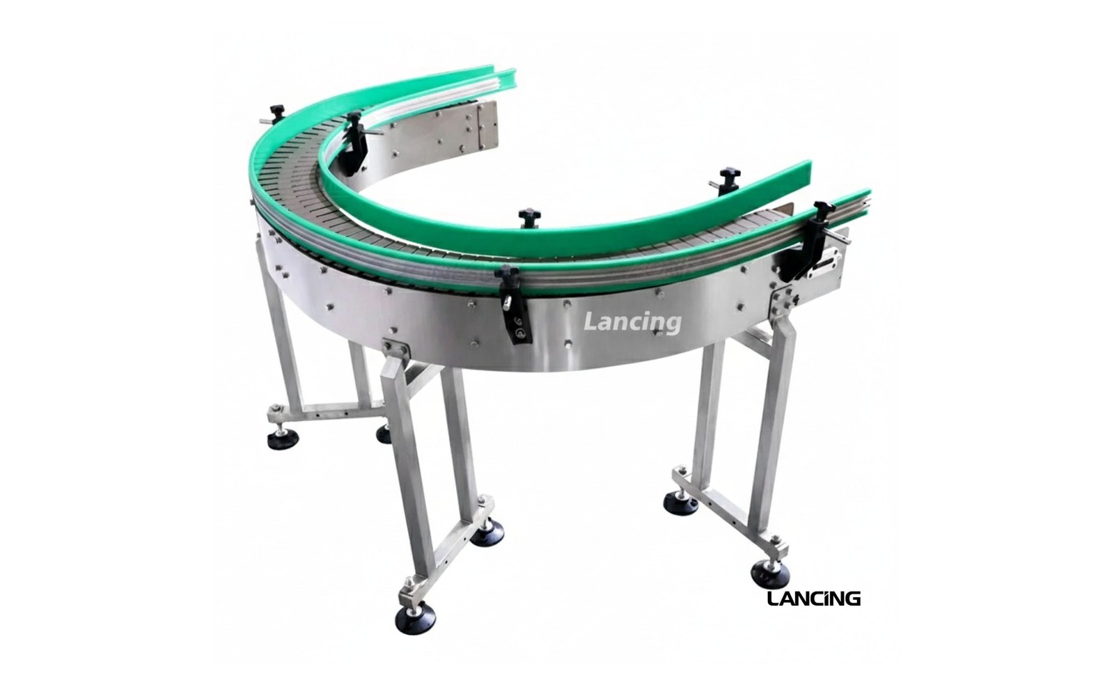 Bottle lines
Stable inline handling for bottles, jars and containers moving through filling, capping and labelling.
Explore →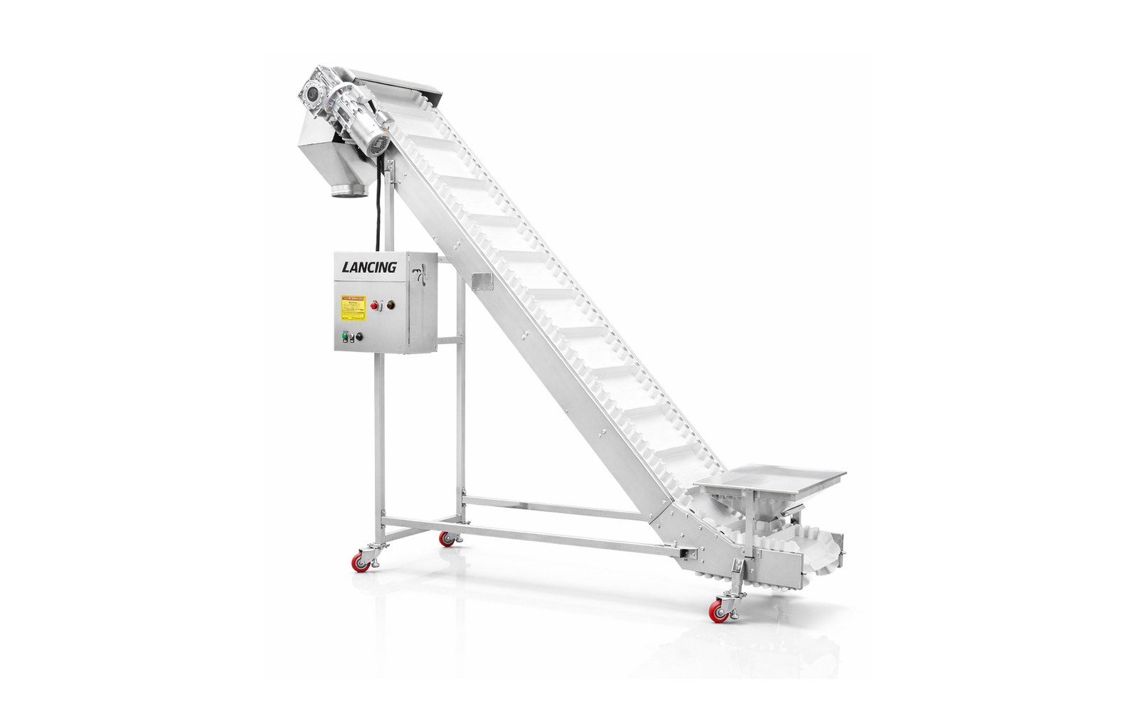 Elevation changes
Move packs between levels with belts, cleats, grip surfaces and layout support for safe transfer.
Explore →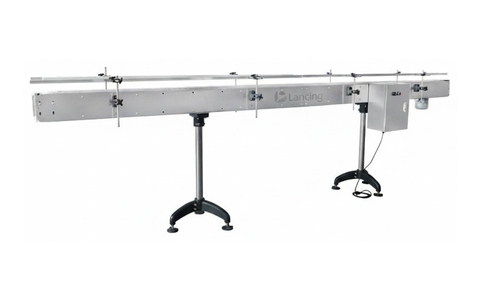 Compare your options
Check pack stability, transfers, widths, speeds, accumulation and integration before choosing a conveyor.
Explore →Clear answers for choosing conveyor options, planning a line layout and preparing quote details.
They influence machine reliability because product spacing, guide alignment and transfer stability affect how the next machine receives the pack.
Yes. Outfeed sections can be planned with inspection, coding verification, reject lanes or manual checking points.
Send pack dimensions, filled weight, line speed, available footprint, infeed and outfeed heights, photos of the existing line and details of connected machines.
Send your product details, line speed and available space to get advice on the conveyor route that fits your packaging line.
An infeed or outfeed conveyor has to do more than reach the next machine. It must present the product at the correct height, direction, pitch and speed, and respond correctly when either machine starts, stops, faults or blocks. Treat each interface as its own mechanical and controls schedule.
The machine manual or supplier drawing should provide the preferred working height, transfer arrangement, product-entry window and control signals where available. Site measurements are still needed for existing equipment, because installed heights, guards and access can differ from an old drawing.
Show the belt or chain surfaces, transfer plate or gap, side-guide transitions and the product outline at the point of hand-off. Include the smallest base, tallest centre of gravity and any projecting pump, handle, cap or seal. A plan view alone can hide a height step or unsupported base feature that causes repeated jams.
Product pitch may be generated by speed differential, gating, timing devices or the upstream machine. State which device owns spacing and what happens when products arrive too close together. For checkweighing, coding or inspection, stable presentation can be more important than conveyor top speed.
Typical interface discussions include run permissive, ready, fault, blocked, starved, full, reject and emergency-stop status. The actual signals depend on the machinery and responsible controls parties. Define whether the conveyor stops immediately, runs on to clear a zone, slows, accumulates or inhibits upstream production for each state.
Use checkweigher integration for weighing and reject interfaces, and coding and inspection conveyors for sensor, encoder and print-presentation detail. Complete line control ownership is covered more broadly by Packaging Line Integration.
| Interface field | Information to record | Acceptance evidence |
|---|---|---|
| Upstream and downstream equipment | Supplier, model, product-flow direction and responsible contact. | Current drawings or measured installation. |
| Working height and transfer geometry | Datum height, gap, overlap, support and guide transition. | Dimensioned detail and sample trial. |
| Product presentation | Orientation, pitch, lane, entry window and allowable contact. | Full format range at agreed rates. |
| Speed relationship | Normal, minimum, maximum, acceleration and recovery condition. | Machine-rate schedule and timed run. |
| Sensors and devices | Photoeye type, position, gate, reject, encoder or other device. | Functional test with difficult products. |
| Control signals | Ready, run, fault, blocked, starved, full and reset behaviour. | Approved signal list and sequence test. |
| Safety interface | Emergency stop, guard circuit, isolators and responsibility boundaries. | Project risk assessment and functional verification. |
| Access and maintenance | Guard removal, sensor adjustment, clearing and changeover space. | Layout review and operator walk-through. |
Run products from the upstream machine into the conveyor and from the conveyor into the downstream machine. Then create the states most likely to cause production loss: no product, closely spaced product, blocked downstream, upstream stop, downstream fault, reject event and normal restart. The objective is controlled recovery without repeated manual clearing.
A photoeye should be proven with the actual colour, transparency, reflectivity and spacing range. A VFD setting should be recorded with the corresponding product rate. If the conveyor carries several formats, changeover settings should be marked or documented so they can be repeated by operators.
Where the main requirement is bulk bottle feeding or orientation before the line, use Bottle Unscramblers UK. The conveyor hand-off begins after that feeding route has been selected.
These answers define the evidence needed for a reliable specification and quotation.
The pack may encounter a gap, unsupported base feature, guide discontinuity, speed step or different belt/chain surface. A dimensioned product-level detail and sample test are needed.
Control ownership depends on the line architecture. It may be local, controlled by one neighbouring machine or coordinated by a line controller. The signal list and safety responsibility must be agreed before build.
It can detect products remaining in a defined zone and trigger slowing, stopping, accumulation or an upstream inhibit. Position, timer and response should be proven with the actual product range.
Often yes, after checking installed height, transfer geometry, product entry requirements, controls, guarding, condition and available access. Do not rely only on the original machine brochure.
Test normal flow, no-product and close-product conditions, downstream block, upstream stop, faults, rejects, reset and restart with the agreed products and rates.
An infeed or outfeed conveyor sits between two equipment control systems as well as two mechanical interfaces. The line must define which machine owns the conveyor, where the speed reference originates, which signals permit running and how the section reacts to starvation, downstream blocking, faults and emergency stops. Leaving those decisions until commissioning turns a mechanical transfer into a controls dispute.
Use one functional description and one signal schedule for the complete interface. Signal names alone are not sufficient: each entry should define the sending device, receiving device, normal state, fault state, delay where applicable and the physical line response.
| Event or signal | Question to resolve | Commissioning evidence |
|---|---|---|
| Run permissive | Which machine confirms that guards, faults and downstream conditions allow movement? | Conveyor starts only in the agreed safe and production-ready state. |
| Speed reference | Fixed setting, local VFD, line reference or machine-generated command? | Stable product pitch and transfer across the required operating range. |
| Product present | Which sensor identifies starvation, a queue or a correctly presented product? | Reliable detection with transparent, reflective and closely spaced formats where relevant. |
| Downstream ready | What condition allows products to leave the interface section? | No flooding of a stopped or unavailable machine. |
| Blocked line | Where is the queue detected and what slows or stops upstream equipment? | Controlled stop before damaging pressure or overflow develops. |
| Fault and reset | Which faults latch, what equipment stops and who authorises reset? | Repeatable recovery without losing product tracking. |
| Emergency-stop interface | Which party supplies the safety circuit and defines the stopping boundary? | Documented response consistent with the agreed risk assessment. |
A photoeye should not be placed only where it is convenient to mount. Its distance from a transfer, gate or machine should allow the control system and conveyor to respond before the product reaches an unsafe or unstable condition. Detection technology must suit the actual product, including transparent bottles, reflective packs, irregular gaps and labels that may change the sensed surface.
For measurement and reject duties, continue to checkweigher conveyor integration. For print or camera presentation, use the coding and inspection conveyor guidance. Mechanical hand-offs should be reviewed against the transfer-point page.
First prove alignment, height, gap, guide transition and steady running with the full product range. Then test starvation, a downstream stop, approaching-full condition, equipment fault, emergency stop and controlled restart. Record the line state, signals, timings, product positions and operator action for each test. The acceptance record should show that the system recovers without uncontrolled release, product loss or repeated manual intervention.
Document responsibilities before installation so commissioning can test an agreed sequence.
The control owner depends on the line architecture, but it must be stated explicitly. One agreed functional description should define run permission, speed reference, ready, blocked, fault and emergency-stop responsibilities.
Product stability also depends on height, gap, base support, guide transition, pitch and the stop or restart state. Equal nominal speeds cannot correct an unsupported base or an abrupt change in product control.
It should provide enough distance and response time for the agreed control action without creating nuisance stops. Confirm the location with the limiting product, sensor technology and actual conveyor stopping behaviour.
A mechanically aligned conveyor can still fail if the connected machines do not exchange clear ready, run, blocked, fault and reset states. Product pitch and stopping distance must match the chosen sensor and control sequence.
For every line state, record which equipment continues, which stops and where product is retained. Define the photoeye purpose and target area rather than placing it only where mounting is convenient. Transparent, reflective, close-spaced or irregular products should be tested at the actual detection point.
Restart deserves a separate test. A sudden release can remove spacing or push unstable packs into the next machine. VFD ramping, upstream permission and downstream readiness should be evaluated together with the mechanical transfer.
Use the controls guide, speed and spacing guide and FAT/SAT checklist.
The conveyor and packaging machine should be treated as one controlled interface wherever product support or line state passes between them.
“Machine ready” should not override evidence that the product path is blocked. The conveyor sequence should distinguish equipment availability from product clearance and hold or stop upstream release until both conditions are satisfied. Define which sensor detects the block, how long it must remain clear and what happens if the condition does not recover.
Product spacing can change between an upstream sensor and the machine because of slip, guide contact, transfer geometry or a speed transition. Measuring at the machine datum shows the condition the process actually receives. State the required leading-edge or centre-to-centre pitch at that point and test the worst-case product during normal flow and restart.
Reset should restore the safety system to a state in which a deliberate restart can be requested; it should not automatically release products or start the complete line. The actual sequence must follow the installed risk assessment and control design. During acceptance, verify the reset and restart behaviour for each interface and confirm that stored product remains controlled.
The project should name an owner for each sensor, its bracket, wiring, logic, adjustment and acceptance. Physical location alone does not establish responsibility. Include the sensors in the mechanical and controls interface schedule so there is no gap between the conveyor supplier and machine supplier when commissioning begins.
An infeed sensor may release a machine, establish pitch or prove that a product has reached the process datum. An outfeed sensor may confirm discharge, control accumulation or track a product towards a reject point. The interface schedule should state who supplies the sensor, who evaluates it and what each machine does when the expected signal is absent.
Where quality equipment returns an accept/reject result, identify the physical pack until rejection is confirmed. Do not assume the conveyor controller and inspection controller share the same product identity without a defined handshake. Use the product-detection guide and reject-handling guide to prepare the evidence.
An infeed may receive several streams, while an outfeed may need to divide accepted products, rejects or alternative formats. The conveyor interface should state which lane can release, which destination is available and how products already inside the controlled zone are recovered after a stop.
Control pitch, destination, queue pressure and fault recovery around the machine infeed or outfeed.
Stop a product at a defined datum and coordinate the conveyor with the connected operation.
Provide usable queue capacity without releasing an uncontrolled surge when the machine recovers.